Home » Without Label » Www.resistor R85 - Ami R85 1981 - Carousel Issue : To change the output voltage of rail 10, change the resistor r85 by using (eq.3).
Www.resistor R85 - Ami R85 1981 - Carousel Issue : To change the output voltage of rail 10, change the resistor r85 by using (eq.3).
Www.resistor R85 - Ami R85 1981 - Carousel Issue : To change the output voltage of rail 10, change the resistor r85 by using (eq.3).. When the user turns the shaft, it turns the resistance on the signal up or down. The blue wires and jumpers come later so ignore them for now. 1) change r85 to 15k, change r103 to 27k. Potentiometers, or pots, are a type of resistor used to control the output signal on an electronic device, like a guitar, amplifier, or speaker. Resistor sd000243 270 ohm 3w metal oxide resistor r107 1 # sd000389 2w 470 metal oxide resistor r15,17 2 sd000241 47 ohm 2w metal oxide resistor r85 1 sd000240 6.8 ohm 1/2w metal oxide resistor r28,49 2 capacitor sd000246 ec8472mh 4700p/250v line capacitor (sec) c88 1 sd000247 py17fy472ml0 4700p/250v line capacitor (pri) c99 1
Potentiometers, or pots, are a type of resistor used to control the output signal on an electronic device, like a guitar, amplifier, or speaker. Anyway i'll post a picture. 1) change r85 to 15k, change r103 to 27k. 2) unsolder wire from point s on board. 20.000 kilohms iii end item identification:
x0xb0x Build Manual - Parts list from www.ladyada.net 3) remove jumper wire parallel to r85 (between r85 and ic8). Contact rl3/b prevents contact r14/a discharging capacitor c19 once contact rl3/b also short circuits resistor r85 to ensure that the thyristors are initially turned full on. It is a smallish 1/10 w resistor, while r83 is in dip package. Working out the optimum compensation was the most difficult part of this project, involving many hours of measurement, experiment and simulation. 0.110 inches minimum and 0.134 inches maximum reliability indicator: Resistor r47 and diode d35 ensure a quick discharge of c19 when the controller rc is returned to the off position via terminal 28 now reconnected to terminal 35 (earth). Configurable resistor marked r86 / r108 pulled high or low (default low) r/b rnb, nand ready & busy. To change the output voltage of rail 10, change the resistor r85 by using (eq.3).
This is ready/busy signal of nand flash memory.
Using the same formula and chosen temperature, you can establish the third point. If the meter indicates zero ohms, the trace hasn't been completely cut. To change the output voltage of rail 11, change the resistor r70 by using (eq.4). (gain) and r85 (volume 1). Problem is color code is not good. They have a small shaft on top that functions like a knob; 2) unsolder wire from point s on board. 1) change r85 to 15k, change r103 to 27k. Zero point eight five ohms resistance. Anyway i'll post a picture. I am confused about what's causing r85 to exceed its power rating.ac_hot is 220 vac. The 16 volt supplies are for the channel switching, and other functions of the amp. 00567167 rpc05t 122 j mtl.film resistor r101 1 00567290 rpc05t 123 j mtl.film resistor r86,89 2 00567301 rpc05t 153 j mtl.film resistor r4 1 00567190 rpc05t 222 j mtl.film resistor r85 1 00567078 rpc05t 271 j mtl.film resistor r102,103,104,105,106,107,108,109 8 00567334 rpc05t 273 j mtl.film resistor r95,99 2
3) remove jumper wire parallel to r85 (between r85 and ic8). 00567167 rpc05t 122 j mtl.film resistor r101 1 00567290 rpc05t 123 j mtl.film resistor r86,89 2 00567301 rpc05t 153 j mtl.film resistor r4 1 00567190 rpc05t 222 j mtl.film resistor r85 1 00567078 rpc05t 271 j mtl.film resistor r102,103,104,105,106,107,108,109 8 00567334 rpc05t 273 j mtl.film resistor r95,99 2 Using the same formula and chosen temperature, you can establish the third point. 2.2 quick start guide (1) ensure that the circuit is correctly connected to the supply and loads before applying any power. Search desired nsn parts in the world largest inventory.
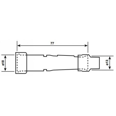
NGK Spark Plug Suppressor from 4x4direct.co.za Ce nncs0, nand chip select0. To change the output voltage of rail 10, change the resistor r85 by using (eq.3). If the meter indicates zero ohms, the trace hasn't been completely cut. Re nnfoe, nand read enable. Wiring up a potentiometer is so easy! 3) remove jumper wire parallel to r85 (between r85 and ic8). The load is an inductive load (an incline motor, rated at 15w). Search desired nsn parts in the world largest inventory.
Configurable resistor marked r86 / r108 pulled high or low (default low) r/b rnb, nand ready & busy.
To change the output voltage of rail 11, change the resistor r70 by using (eq.4). The blue wires and jumpers come later so ignore them for now. 3) remove jumper wire parallel to r85 (between r85 and ic8). Ce nncs0, nand chip select0. Cixi anxon electronic co., ltd is the best doorknob ceramic capacitor,leaded disc ceramic capacitor,rf power capacitor,diode,resistor,relay supplier, we has good quality products & service from china. The load is an inductive load (an incline motor, rated at 15w). Working out the optimum compensation was the most difficult part of this project, involving many hours of measurement, experiment and simulation. Problem is color code is not good. The 3 digit smd resistor code r85 stands for 0.85 ω, in words: Wiring up a potentiometer is so easy! Wiring up a potentiometer is so easy! The load is an inductive load (an incline motor, rated at 15w). Operating temp m55.0 to p150.0 deg c.
To change the output voltage of rail 11, change the resistor r70 by using (eq.4). Configurable resistor marked r85 / r124 pulled high or low (default high) d4 sd4, static memory/nand data bus 4. Resistor r47 and diode d35 ensure a quick discharge of c19 when the controller rc is returned to the off position via terminal 28 now reconnected to terminal 35 (earth). Search desired nsn parts in the world largest inventory. (gain) and r85 (volume 1).
Cymbal - e-licktronic from www.e-licktronic.com Yes, the value of the feedback resistor (r85,86) and the value of the compensation cap (c35,36) would need to be changed, if a different transformer tap is used for feedback. It may last for a few minutes before burning out. 3) remove jumper wire parallel to r85 (between r85 and ic8). Configurable resistor marked r86 / r108 pulled high or low (default low) r/b rnb, nand ready & busy. The 16 volt supplies are for the channel switching, and other functions of the amp. I am confused about what's causing r85 to exceed its power rating.ac_hot is 220 vac. To change the output voltage of rail 11, change the resistor r70 by using (eq.4). Ce nncs0, nand chip select0.
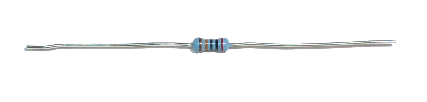
The 3 digit smd resistor code r85 stands for 0.85 ω, in words:
It is a smallish 1/10 w resistor, while r83 is in dip package. 5) solder wire taken from point s to 4.53k resistor, on the end closest to r88. 5) solder wire taken from point s to 4.53k resistor, on the end closest to r88. Using the same formula and chosen temperature, you can establish the third point. Anyway i'll post a picture. If you know the values please share :) thank you. 3) remove jumper wire parallel to r85 (between r85 and ic8). Potentiometers, or pots, are a type of resistor used to control the output signal on an electronic device, like a guitar, amplifier, or speaker. The load is an inductive load (an incline motor, rated at 15w). Resistor r47 and diode d35 ensure a quick discharge of c19 when the controller rc is returned to the off position via terminal 28 now reconnected to terminal 35 (earth). The blue wires and jumpers come later so ignore them for now. To change the output voltage of rail 11, change the resistor r70 by using (eq.4). Configurable resistor marked r86 / r108 pulled high or low (default low) r/b rnb, nand ready & busy.